
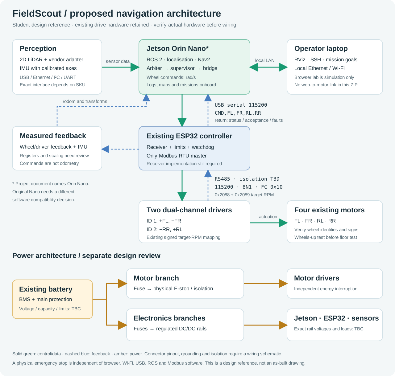
Student objective: design, integrate and validate a LiDAR navigation subsystem that turns a map goal into controlled movement of the existing FieldScout platform. The Jetson performs perception, localisation and planning; the existing ESP32 remains the low-level motor gateway and the only Modbus master. Deliver a repeatable, supervised indoor demonstration by the project's stated 23 December 2026 endpoint.
This brief defines the requested navigation focus. It supersedes the earlier project's suggestion to build new motor drivers: the company now confirms that its motor controller already exists. Dates, numerical targets and unconfirmed component choices below are proposed planning values, to be agreed with the company and SDU supervisor. They are not measured performance claims or purchase authorisations.
Build it in this order
01 · Produce the bill of materials
Start with the downloadable BOM template. Inventory and photograph what is physically available, then identify what must be purchased. Record exact manufacturer part number, revision, interface, voltage, worst-case current, ROS driver, lead time, quantity, supplier quotation, tax/shipping and owner. Compare at least two LiDAR options. Add mounts, cables, cooling, storage, fuses and regulated power—not just the Jetson and LiDAR. Leave unknown prices and inventory as TBC. Exit evidence: reviewed BOM, power estimate, procurement priorities and a list of missing information.
02 · Draw the complete block diagram
Use the architecture diagram as a starting point, then replace every provisional interface and supply label with a verified choice. Show data arrows, message direction and units, physical connectors, power rails, fuse branches, emergency-stop motor-power path, common-reference/isolation boundaries and the owner of each function. Include telemetry returning from the drivers/ESP32 to the Jetson. Exit evidence: one readable system diagram plus a connector/pin table. A logical block diagram is not a wiring schematic.
03 · Establish the hardware baseline
Read the labels on the Jetson, ESP32, drivers, motors and battery. Measure wheel radius, effective track, footprint and loaded mass. Confirm driver IDs and wheel polarity with the wheels lifted. The Lua scene uses radius 0.0535 m, track 0.250 m and total mass 26 kg, while the brochure gives different overall specifications. Use the Lua dimensions only as a starting simulation profile; do not infer the physical battery voltage from the Lua's 24 V motor description. Exit evidence: dated configuration sheet and a wheel-mapping video.
04 · Bring up compute, power and sensors
Choose a supported Jetson/JetPack/ROS combination from the matrix below. Install the selected LiDAR's ROS 2 driver, configure a persistent device name, and visualise /scan in RViz. Establish CPU, temperature, supply-voltage and scan-rate logs. Secure cables and position the LiDAR above the robot's own obstructions without moving the centre of mass unnecessarily. Exit evidence: stationary 10-minute scan and power log, with correct ranges and axes.
05 · Implement the controller interface before autonomy
Obtain or implement an ESP32 receiver for the Lua-style ASCII wheel-command contract; neither supplied .ino currently implements it. Keep the tested wheel mapping and Modbus writes. Start without motor power, check parsing, finite values, four-wheel order, limits, acknowledgements, stale-command timeout and a zero-only handshake. Then repeat wheels-up. Disable the demo's automatic startup sequence in the eventual navigation firmware. Exit evidence: packet captures and fault-test results, including an unplugged USB test.
06 · Create odometry and transforms
Read actual encoder/driver feedback only after confirming the model's register map and scaling. Fuse measured wheel odometry and IMU data if available. Publish /odom and the required transforms. Calibrate distance and turn scale on the actual surface. Commanded wheel speed is not measured odometry. Exit evidence: straight-line and turn tests, a stable TF tree and a documented feedback source.
07 · Map the first operating area
Choose a controlled indoor test course with solid, visible landmarks and no public traffic. Teleoperate slowly, record a rosbag and build a 2D map using a supported SLAM package such as SLAM Toolbox. Check loop closure, map scale, missing walls and scan shadows. Save the map image, YAML, sensor extrinsics, configuration and source commit. Exit evidence: repeatable saved map and a replayable dataset.
08 · Localise in the saved map
Use AMCL or the selected SLAM package's localisation mode, with one publisher responsible for map → odom. Set the initial pose and verify recovery after restart. Challenge it with a corridor, partial occlusion and an intentionally wrong initial pose. Stop if localisation is stale or unreliable. Exit evidence: repeated localisation results against independent surveyed marks.
09 · Integrate Nav2 and command arbitration
Configure the measured footprint, inflated obstacles, conservative velocity limits, planner, controller and recovery behaviour. Route planner and manual inputs through one arbiter, then command shaping/collision supervision, then the Jetson–ESP32 bridge. Do not let two nodes write independently to the motor port. Exit evidence: a single waypoint reached repeatedly and manual takeover that cancels autonomy.
10 · Demonstrate missions and fault handling
Run a three-waypoint mission with a planned stop at each goal. Add a stationary obstacle, then a blocked aisle. Use updated obstacle data to find a feasible detour; if no valid route remains, stop and report a blocked route. Validate the selected planner and controller on the actual robot before claiming physical obstacle avoidance. Test lost LiDAR, stale odometry, bridge termination, USB disconnect, reboot, duplicate command and emergency stop. Use inert test objects; do not use a person or animal as the test obstacle. Exit evidence: completed acceptance matrix and timed videos correlated with logs.
11 · Validate beyond the demonstration
Repeat the same route and report all trials, including failures and interventions. Measure goal error, completion rate, minimum clearance, stop distance, latency, power and CPU load. Only expand to a greenhouse or outdoor area after the indoor baseline passes and the sensors, ground conditions and enclosure are suitable. Exit evidence: reproducible results with uncertainty and a clear operating envelope.
12 · Hand over a reproducible system
Deliver the BOM, electrical diagram, mounts/CAD, hardware inventory, pinned software versions, source, build instructions, receiver/bridge protocol, calibration files, map, test logs, issue list and a short operator guide. Include a clean-start demo video and explain exactly which capabilities remain simulated. Exit evidence: another team member can rebuild and repeat the demonstration from the handover package.
The hardware and software architecture
Inspect the complete signal and power architecture above. Use its editable SVG as the starting point for your own block diagram.
| Connection | Proposed interface | Responsibility and check |
|---|---|---|
| 2D LiDAR → Jetson | Vendor USB/UART adapter or Ethernet, depending on exact LiDAR SKU | Produce timestamped sensor_msgs/LaserScan; verify scan frame and actual rate. A TTL UART is not RS485. |
| IMU → Jetson | Supported USB, I²C or UART interface | Publish measured angular velocity/acceleration with calibrated axes; avoid unverified magnetic yaw near motors. |
| Laptop ↔ Jetson | Local Ethernet or Wi-Fi | RViz, SSH, logs and mission goals. Navigation should run onboard; loss of the laptop is not a reason to retain a stale manual command. |
| Jetson ↔ ESP32 | USB serial, 115200 baud, newline-terminated ASCII | Send logical wheel angular velocities; receive status/fault information. Separate this port from the motor RS485 bus. |
| ESP32 ↔ motor drivers | Existing RS485 transceiver; verify isolation, Modbus RTU, 115200 8N1 | ESP32 is the single bus master; driver IDs 1 and 2. GPIO18 RX and GPIO17 TX are MCU-side UART pins, not direct A/B wiring. |
| Driver feedback → Jetson | Validated Modbus readback → ESP32 telemetry → serial bridge | Register addresses, encoder scaling and odometry feedback messages remain to be specified. Do not invent them from command registers. |
| Battery → all subsystems | Protected motor branch and separately fused regulated logic/sensor branches | Verify chemistry, full-charge range, BMS, grounding, current and transient behaviour before selecting converters. |
Use the existing ESP32 gateway as the default. A direct Jetson-to-RS485 alternative is possible only if the ESP32 relinquishes the bus and the replacement implements the same limits, watchdog, acknowledgements and fault handling. Two Modbus masters on the same RTU bus are not the proposed design.
Select the actual Jetson before choosing the OS
The user says “Jetson Nano”; the project document and slide 4 specify Jetson Orin Nano. These names identify different generations. Photograph the board/module label before buying, flashing or budgeting. Official compatibility pages were checked on 21 September 2026.
| Hardware | Software path | Decision |
|---|---|---|
| Original Jetson Nano | Legacy JetPack 4.x / Ubuntu 18.04 family | Do not assume a native current Humble/Jazzy installation. Keep it only with a documented, tested integration plan; modern containers do not change the underlying board-support limitations. Prefer an Orin Nano for this new student build. |
| Jetson Orin Nano | JetPack 6.2.2 / Ubuntu 22.04 / ROS 2 Humble | Conservative proposed course baseline; verify the carrier, firmware update procedure and chosen sensor driver. Humble's listed support ends May 2027, so document a maintenance plan after the course. |
| Jetson Orin Nano | JetPack 7.2.1 / Ubuntu 24.04 / ROS 2 Jazzy | Current supported hardware/OS family alternative with longer ROS support (Jazzy to May 2029). Prove LiDAR, IMU and serial packages together before freezing this combination. NVIDIA's current release uses a different install flow; do not follow an old SD-card tutorial. |
These are compatible platform families, not evidence that FieldScout has been validated on them. Pin the exact JetPack, ROS distribution, package versions and Git commits used in your successful bench test. Do not mix Humble configuration snippets with Jazzy defaults without checking them. For the velocity bridge, explicitly check whether the selected chain uses geometry_msgs/Twist or TwistStamped; configure one type consistently.
Minimum BOM and selection rules
| Item | Quantity | Selection criterion | Initial status |
|---|---|---|---|
| Existing chassis, four motors, two dual-channel drivers and ESP32 | 1 set | Preserve working drive hardware; verify labels, pinout and condition | Company states available; handover inventory/date TBC |
| Jetson Orin Nano, carrier and cooling | 1 | Exact board revision, memory, connectors and supported software recorded | Availability TBC |
| 2D 360° LiDAR and vendor interface cable/adapter | 1 | Near-field blind range, angular resolution, scan rate, dark objects, sunlight, driver support and field of view | Purchase selection TBC |
| IMU | 1 | Supported ROS driver, timestamp quality, mounting axes and bias stability | Existing inventory TBC |
| Storage | 1 | Supported media, capacity for rosbag recording and reliable write performance | TBC |
| Regulated power converters and distribution | 1 set | Verified battery range; startup peaks, conversion loss, fuses and cooling | TBC after measurement |
| USB data cables and locking/strain-relieved connectors | 1 set | Correct data capability, routing, EMI and no connector tension | TBC |
| Mounts, fasteners and enclosure provisions | 1 set | LiDAR visibility, service access, stability and cooling | Student design |
| Physical emergency stop and power isolation provisions | 1 set | Inspect existing design; motor energy interruption independent of software | Verify existing hardware |
| Test equipment and course obstacles | 1 set | Power measurement, wheel-lift support, measured ground marks and inert targets | Lab access TBC |
LiDAR candidates for evaluation, not purchase commitments: SLAMTEC RPLIDAR A1 is a low-cost 2D bench/indoor candidate; RPLIDAR S2 is a candidate where sunlight/outdoor performance matters. SLAMTEC publishes a ROS 2 driver that lists both families. Compare the exact SKU, interface adapter, minimum range and datasheet conditions; a product-family name is not a complete BOM. Neither product choice alone provides a certified protective sensing function. RTK-GNSS, RGB camera, LoRaWAN, solar charging, docking and environmental payloads are optional extensions after navigation passes.
For each supply branch measure normal and peak load. Estimate mission energy using E_required = sum(P_average × duty_fraction) × mission_hours, then account for converter losses and the battery's allowed usable energy. Rate wires, connectors and fuses from verified current and cable limits. No battery runtime, 5 V rail capacity or motor voltage is assumed from the brochure.
Frames, data and control contract
The ROS convention is x forward, y left and z up. Positive yaw rate turns left/counter-clockwise. The Lua joystick uses positive steering for right; a bridge must not copy that joystick sign into angular.z.
| Transform or topic | Owner | Required evidence |
|---|---|---|
map → odom | AMCL or SLAM localisation, one owner | Stable map alignment; no duplicate TF publisher |
odom → base_link | Wheel/IMU estimator | Continuous local motion estimate and realistic covariance |
base_link → laser, base_link → imu_link | URDF/robot_state_publisher or static TF | Measured position and orientation; timestamp consistency |
/scan | LiDAR driver | Correct frame, limits, angular direction and scan age |
/odom, /imu/data | Sensor/estimation nodes | Measured data, stated units, update rate and covariance |
| Selected velocity → bridge | Command arbiter and supervisor | One final stream; metres/second and radians/second |
| Wheel telemetry/status | ESP32 bridge | Separate commanded, accepted and measured values |
Nav2 needs the transforms and a suitable odometry source; adding a LiDAR and drawing waypoints is not enough. Skid-steer wheel slip makes the effective track surface-dependent. If driver feedback cannot be obtained, evaluate a documented LiDAR/visual odometry alternative and its failure cases; do not label integrated command speeds as measured robot motion.
For an initial differential/skid-steer model with radius r and effective track b:
omega_left = (v - yaw_rate × b / 2) / r
omega_right = (v + yaw_rate × b / 2) / r
CMD,FL,FR,RL,RR\n = CMD,omega_left,omega_right,omega_left,omega_right\n
Values in the ASCII packet are rad/s, positive in robot-forward convention. Convert inside the ESP32 with RPM = omega × 60 / (2π), apply an explicitly documented rounding policy and clamp before signed 16-bit encoding. Driver polarity belongs in one layer only:
| Driver/channel | Physical wheel | Signed RPM sent to driver |
|---|---|---|
| ID 1 / first register | Front left | +FL |
| ID 1 / second register | Front right | -FR |
| ID 2 / first register | Rear right | -RR |
| ID 2 / second register | Rear left | +RL |
The supplied demo writes two consecutive target registers starting at 0x2088 with function 0x10; words are high byte first, signed negative RPM uses two's complement, and CRC16 bytes are low byte first. The second driver order is rear right then rear left. A write acknowledgement establishes register acceptance, not physical movement or measured speed.
Example using the unverified Lua geometry r=0.0535 m, b=0.250 m: v=0.20 m/s, yaw_rate=+0.50 rad/s gives left 2.570 rad/s, right 4.907 rad/s and CMD,2.570,4.907,2.570,4.907\n. The right wheels advance faster, so the robot turns left. The message inspector can show the corresponding rounded RPM and RTU bytes without connecting to real hardware.
What is missing in the supplied firmware
RobotLuaScript.txt expects ESP32_READY, HELLO, ACK,HELLO and streamed CMD lines at 20 Hz, with a stated 400 ms receiver watchdog. That is evidence of the Lua contract, not proof that the supplied ESP32 files implement it.
The 9 September .ino prints an “ESP32 LIVE” message once per second and never parses commands. The 10 September .ino drives an automatic repeating demo and implements operator commands such as PAUSE, RESUME and ESTOP, but has no four-wheel CMD parser. It also uses a 100 ms refresh constant despite stale comments/startup text referring to 250 ms. Do not flash either file expecting Nav2 control or a working command timeout.
The navigation receiver must start stopped with motion disabled, require explicit enable after a zero-command handshake, validate complete bounded lines and reject NaN/Inf, wrong field counts and out-of-range values. It must zero stale targets using a monotonic timer, supervise failed driver acknowledgements, and never resume motion automatically after reboot, reconnect or fault clearance. Use the Lua's 400 ms as a proposed upper timeout for compatibility testing; validate actual stop latency, because blocking Modbus retries and deceleration affect it. A failure to transmit a zero command over a broken bus cannot guarantee a physical stop; verify an independent motor-power stop path.
Staged acceptance and evidence
The downloadable acceptance matrix contains proposed targets for a low-speed indoor prototype, not a claim of achieved safety or regulatory compliance. Start ground testing at 0.10 m/s, with a proposed initial ceiling of 0.20 m/s only after stopping tests pass. Keep the Lua's 150 RPM physical-stream cap as an additional upper bound; it is not an appropriate default floor-test speed. Reduce limits when clearance or sensing is insufficient.
Derive obstacle stopping margins from measured values: distance >= speed × total_latency + speed² / (2 × minimum_deceleration) + margin. This formula is only a planning approximation; verify actual stopping on the worst intended floor, load and battery condition. Measure clearance from the robot footprint, not from the LiDAR origin. A 2D scan can miss obstacles below/above its plane, glass, drop-offs and some dark surfaces. Constrain the course accordingly or add suitable sensors.
Suggested first demonstration: three goals on a documented indoor course, ten repeat runs, goal position error at most 0.20 m and heading error at most 15°, at least nine complete runs without intervention, and zero contacts in all runs. Record every failed run. Proposed static clearance is at least 0.25 m from the measured footprint; the actual required margin may need to be larger after stopping and perception tests. Fault tests pass only when the documented timeout and measured stopping bound are both met. Deliberate fault clearance must leave the robot stopped until a fresh operator enable and command.
Team ownership and milestone proposal
| Planning window | Review evidence | Suggested lead |
|---|---|---|
| 21–28 September | BOM, block diagram, known/unknown register and agreed scope | Whole team; systems lead coordinates |
| By 12 October | Sensor bench logs, power budget, exact hardware/software baseline | Electronics + software |
| By 26 October | Wheels-up bridge tests, encoder/IMU path, stop/fault evidence | Embedded + controls |
| By 9 November | Saved map, localisation repeatability, calibrated footprint | Navigation + mechanics |
| By 23 November | First supervised three-waypoint mission and obstacle response | Navigation + integration |
| By 7 December | Repeated acceptance runs, failure analysis and design freeze | Test lead + whole team |
| By 14 December | Rebuild rehearsal, complete documentation and demo backup | Whole team |
| By 23 December | Final functional prototype evidence, report and handover | Whole team |
These dates do not promise equipment delivery or company availability. Replan with the supervisor if hardware arrives late; continue with logs, the browser lab and a validated software simulation meanwhile. Keep business work bounded to intended research users, competitor comparison and cost/value evidence for this navigation prototype. For each Monday meeting bring a one-page progress note, one reproducible result, current blockers and the next acceptance test. Record decisions with an owner and due date.
References and source boundaries
Source review date: 21 September 2026. Configuration recommendations are engineering proposals informed by the sources below; FieldScout-specific wiring, geometry, calibration and firmware must still be checked on the actual unit.
- The project PDF, page 1, establishes the autonomous-navigation task and layered platform concept; its exploded rendering shows the modular mechanical intent, not as-built wiring. Page 2 lists the earlier broad EXT scope and explicitly names Orin Nano.
- Presentation slide 4 depicts the target sensor → Jetson → ESP32 → motor-driver architecture. Slide 6 reports brochure specifications; they are not accepted test results. Slide 8 distinguishes the physical printed base from complete autonomy.
- The two original
.inofiles and Lua script establish the interface gap, wheel polarity and demonstration behaviour described above. - NVIDIA JetPack 6.2.2: https://developer.nvidia.com/embedded/jetpack-sdk-622
- NVIDIA current JetPack downloads: https://developer.nvidia.com/embedded/jetpack/downloads
- NVIDIA legacy JetPack 4.6.1 (Nano family): https://developer.nvidia.com/embedded/jetpack-sdk-461
- ROS target platforms and support periods: https://www.ros.org/reps/rep-2000.html ; upstream source mirror: https://github.com/ros-infrastructure/rep/blob/master/rep-2000.rst
- Nav2 transforms: https://docs.nav2.org/jazzy/configuration_and_development/first_time_robot_setup_guide/transformation/setup_transforms/
- Nav2 odometry: https://docs.nav2.org/jazzy/configuration_and_development/first_time_robot_setup_guide/odom/setup_odom_gz/
- Nav2 mapping/localisation: https://docs.nav2.org/jazzy/configuration_and_development/first_time_robot_setup_guide/sensors/mapping_localization/
- Nav2 collision-monitor configuration: https://docs.nav2.org/jazzy/configuration_and_development/configuration_guide/core_servers/collision_monitor/configuring_collision_monitor_node/
- SLAMTEC LiDAR comparison starting points: https://www.slamtec.com/en/lidar/a1 ; https://www.slamtec.com/en/s2
- Manufacturer ROS 2 driver: https://github.com/Slamtec/sllidar_ros2
The linked Nav2 guides currently render as Jazzy documentation. Use the chosen distribution's matching package docs for installation and parameters. This package's browser lab demonstrates movement, synthetic LiDAR, A* route planning and online detours around newly detected boxes, with generated wheel-command previews. It uses an ideal pose and exact simulated obstacle outlines; it does not implement SLAM or DWA, supply a tested robot receiver, or validate physical odometry and autonomy. Publishing motor commands to a web-hosted JSON endpoint is a later phase and is not enabled by this assignment.